


With freeboard
Packed beds
Other technologies
Polishers
Construction material
Nozzles & fractals
Backwash columns
Ion exchange columns
Introduction
Ion exchange resins are used in columns, in principle similar to those used for sand filters or activated carbon. These are pressure vessels, usually made of rubber-lined steel. Small units are made of fiberglass reinforced plastic, and units used in the food industry are often made of stainless steel. A typical ion exchange column with co-flow regeneration is represented below:
Co-flow regenerated column
Some explanations about the details shown in the picture:
- The water enters from the top of the column. So as not to disturb the surface of the resin bed, the incoming water stream is stopped by a simple jet breaker.
- The column has a large freeboard, usually about the same height as the resin bed, so that the resin can be backwashed inside the column to remove suspended solids accumulated on the bed surface.
- A manhole (shown on the left side) is necessary to inspect and possibly repair the column inside.
- Two sight glasses are also shown, one at the top, one at the level of the resin bed surface.
- An air vent is also necessary at the top, to empty the column by draining the water out for inspection or a resin change.
- One of the most important features of the vessel is the collector at the bottom: nowadays, one of the most popular types of collector is a plate with densely distributed nozzles (see at bottom of page).
- The reinforced plate disk of steel onto which the nozzles are screwed.
- It is supported by poles or L-shaped beams (here two poles are visible).
- A regenerant distributor is sometimes — but not always — mounted in the middle of the vessel to ensure a uniform distribution of the regenerant. In absence of such a collector, the regenerant is introduced from the top of the column, which results in some dilution of the chemicals.
Most of the features of the above column (vent, sight glasses, nozzle plates, manhole) are common to many types of column, regenerated in co-flow or in reverse flow. You will find here the most common vessel designs used in water treatment, including:
- Columns with freeboard
- Co-flow regenerated vessels
- Reverse flow regeneration with air hold-down
- Reverse flow regeneration with water hold-down
- Stratabed columns
- Split-flow columns
- Packed bed columns
- AmberpackTM and floating beds
- Multi-compartment Amberpack
- UpcoreTM (Amberpack Reverse)
- StratapackTM
- Some other technologies
- EconexTM (Italba)
- ReCoFlowTM (Ecotec)
- ISEPTM (Calgon Carbon)
- Polishers
- Mixed bed units
- TriobedTM
- Amberpack SandwichTM
- MultistepTM (Bayer)
- TripolTM (Vivendi/Permutit)
The bed must be compacted
A resin bed is only fluidised, by backwashing, for two purposes:
- To remove resin and foreign particles from the bed surface and decompact the bed after a long period of operation.
- To separate resins before regeneration in a mixed bed or separate strong from weak resin in a Stratabed.

Columns with freeboard
The main advantage of having a freeboard in the vessel is to allow for resin backwash. This is useful when the feed water contains suspended matter. The disadvantage of columns with freeboard is wasted space, and complicated or fragile internals.
Co-flow regenerated vessels
See the picture at the top of the page. Co-flow columns are exhausted from top to bottom and regenerated from top to bottom as well.
The freeboard provides space for backwashing the resin bed, when required.
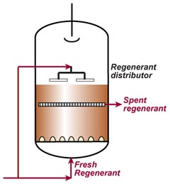
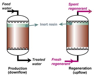
Reverse flow regenerated vessels with hold-down
See the page about regeneration methods. Reverse flow regenerated (RFR) vessels with freeboard are similar in concept to co-flow regenerated (CFR) units, except for a regenerant collector at the top of the resin bed. They are exhausted downflow and regenerated upflow. The bed must be kept compacted and must not fluidise during regeneration. For this reason, the regenerant cannot be removed from the top or the column but must be extracted through a collector just above the resin bed. The two main types of columns with hold-down technology are compacted with air or water. As the bed must be kept compact during regeneration, extra resin is required to cover the collector. This can be inert or inactive resin (see below).
In the following pictures, some details have been omitted, such as sight glasses, valves, vents, and manholes. Thes are essentially the same as those shown in the co-flow picture at the top of this page.
In production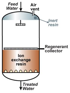 |
In regeneration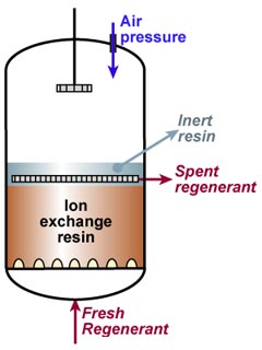 |
Instead of pushing air into the unit (whereby the compressed air is often warm), you can also suck the liquid using a hydro-ejector. In this case, as the tendency of dehydrating the resin is lower, ion exchange resin can be used to cover the regenerant collector instead of inert material.
Air hold-down is suitable for regeneration flow rates up to 10 m/h, thus fine for sulphuric acid regeneration at a low concentration.
The depth of inert or inactive resin must be enough to cover the regenerant collector at the beginning as well as the end of regeneration; resin swelling must be taken into account when determining its volume.
In production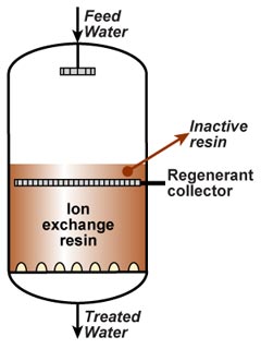 |
In regeneration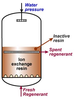 |
Water hold-down units can be operated only at very low regeneration flow rates otherwise the hydraulic system is unstable.
The downward flow rate of the hold-down stream must be adjusted as a function of the upward regenerant injection flow rate, density of the regenerant, density of the resin and acceptable contact time, which should not be too long for sulphuric acid regeneration. Although not a rule, it seems that the hold-down flow rate is often equal to the flow rate of the regenerant solution. No inert material is required. The resin volume must be calculated including the amount of inactive resin that must always cover the collector.
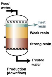
Stratified beds
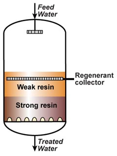
These are hold-down units containing a pair of cation or anion resins: the weakly functional resin has a smaller particle size, and its density is lower than that of the strongly functional resin allows the two components to be kept separated. Some mixing of both layers at the interface is inevitable, though, and periodical re-separation is required. The stratified bed technology saves a column and brings the benefit of a good regeneration efficiency. As the weak resin always has a density smaller than the strong base, stratified bed must always be regenerated in reverse flow. For co-flow regeneration, two separate columns are necessary.
Stratified beds are also called layered beds. StratabedTM is a trademark of Dow.
Air and water hold-down, including Stratabed
As we have just seen, additional resin is required, either inert (air holddown) or inactive ion exchange resin (water holddown).
Split-flow units
In split-flow vessels, regeneration is carried out simultaneously from the top and from the bottom of the bed. The regenerant collector is located in the upper third of the resin bed. An additional regenerant distributor is required above the resin bed. The idea is to allow the upper part of the bed to be backwashed to remove accumulated debris without disturbing the lower layers of the bed that are responsible for the good treated water quality. There is no inert or inactive resin, and the system does not consume extra water, but is more complicated and the regeneration flows are sometimes difficult to adjust.
Resins used in vessels with freeboard
Practically all resins can be used. In practice, standard grades are often chosen for co-flow units, because they are cheaper.
For reverse flow regeneration, uniform particle size resins are often selected due to their better hydraulic characteristics and to a slightly higher operating capacity compared to the standard grades. For Stratabed units, a fine specially graded weak resin is required, as well as a high density and coarser strong resin.
Packed bed units
Those have no freeboard — although a little space must be allowed to accommodate resin swelling — and no internals that obstruct the hydraulic flow and can be easily damaged. The vessels are thus smaller and cheaper, and the resin depth is usually higher than in a column with freeboard. This offers a benefit for strongly acidic and strongly basic resins, which have a higher operating capacity when the bed depth is high. Also, there is no need for an inactive resin, although Bayer's floating bed and Dow's Upcore use an inert material. Of course, the resin can no longer be backwashed in situ due to the absence of freeboard. A separate backwash column is necessary in most cases.
Floating bed units
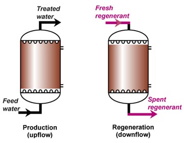
Amberpack in service and regeneration
Called "Schwebebett" by Bayer AG in 1963, this design has upflow loaded, downflow regenerated columns in which the bed was initially partially fluidised. The floating bed technology has been a big success since the mid 1970's has been adopted, with some variations, by most of the European OEMs. Today, these units are fully packed with practically no fluidised resin.
Bayer's Schwebebett (called WS system in some countries) uses an inert floating material at the top of the resin chamber. It cannot be backwashed.
AmberpackTM
Amberpack with double chamber
The Amberpack system of Rohm and Haas is a variation of the floating bed and enables resin transfer to a backwashing column. The ion exchange vessels are similar to Bayer's Schwebebett units, the differences being the absence of inert floating material and the presence of at least two transfer ports per resin chamber, through which resins can be taken out for backwashing. The resins are exhausted upflow and regenerated downflow.
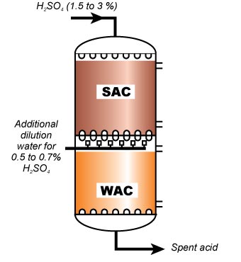
In multicompartment Amberpack columns, two (sometimes three) resins are separated by a plate fitted with double nozzles. This is the ideal system for WBA/SBA and for WAC/SAC combinations: it gives the best efficiency and treated water quality. Each compartent has two transfer ports for external backwashing.
The WAC/SAC combination with sulphuric acid regeneration requires a special version with secondary dilution.

A full Amberpack demineralisation line followed by a mixed bed polisher
UpcoreTM
Upcore column in service and regeneration
UpCoRe stands for "Upflow Countercurrent Regeneration". Dow licensed this technology from the Dutch engineering company Esmil in the late 1970s. The units are exhausted downflow and regenerated upflow. A special inert polymer called Dowex Upcore IF62 fills the upper part of the columns.
Dow claim that their system is "self-cleaning", and that suspended solids accumulated during the exhaustion run escape during the first stage of regeneration, but this is only partially true: the system is not capable of eliminating large amounts of suspended matter, unlike Amberpack with its dedicated backwashing tower.
Besides, upflow regeneration is more difficult than downflow, particularly with hydrochloric acid, because of the high velocity required to compact the bed and the resulting short contact time. This system consumes a little more water, as an additional step is required to compact the bed against the top nozzle plate before regenerant injection.
Upcore is also available as Amberpack Reverse, the main difference being the presence of a backwash column as a safety feature.
Upcore is useful when the plant works intermittently or when large flow rate variations are expected.
StratapackTM
A Stratapack vessel
Stratapack columns, which are Amberpack Reverse units in the Stratabed fashion, and offer the advantages of both. Inert resin is necessary in view of the relatively fine particle size of the weak base or weak acid resin. The column has three transfer ports. The system is also available as Upcore layered bed.
Stratapack cation units are not recommended with sulphuric acid regeneration.
Because a little mixing at the interface cannot be prevented, Stratapack is not quite as efficient as a double-compartment Amberpack. Additionally, it consumes a little more water, like Amberpack Reverse. To minimise the effect of resin mixing, a higher dosage of regenerant is often used.
The common characteristic of all Amberpack systems is the presence of a backwash column, which is an essential safety device to ensure smooth operation of the water treatment plant.
Resins used in packed bed units
Only uniform or semi-uniform grades are suitable. Standard grades will cause serious trouble due to the fine bead fraction. For Stratapack units, a fine specially graded weak resin is required, as well as a high density and coarser strong resin.
Some other technologies
Many OEMs have their own proprietary design. Only a few will be mentioned here.
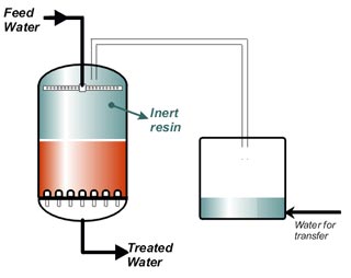
The Econex system
This system was developed in the 1970s by Italba-Ionics and Davy-Bamag. The columns have a freeboard, but in normal operation it is filled with inert material so the columns do not need an air or water hold-down during regeneration. When the resin has to be backwashed, the inert is extracted to a holding tank and backwashing is performed in the ion exchange column.
The columns are simple, but large and a transfer system is needed. Some units have double chamber anion columns to house a WBA above and a SBA below.
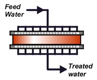
A ReCoFlo unit
This technology was developed by the Canadian Ecotec Corporation. The columns are very shallow, with a bed depth of typically only about 15 cm (6 inches). Cycles are very short, the service run being only about 20 minutes. Special, fine resins are used. This technology was mainly applied in the surface treatment industry.

A simplified ISEP system
ISEP is a simulated moving bed, operating in a quasi continuous, stepwise fashion. It was developed by the US company Advanced Separation Technologies (AST), now a subsidiary of Calgon Carbon. The columns typically 30 of them) are arranged in a carrousel (merry-go-round). The feed and elution solutions are connected to a stationary upper distributor fitted with typically 20 ports, and the raffinate as well as the extract are connected to a lower stationary connector fitted with the same number of ports. The columns themselves are on a rotating frame. The carrousel rotates continuously at a speed of 0.1 to 1.5 revolutions per hour, and the ports are thus successively connected to all columns. A simplified schema is shown here with only 8 columns and 6 inlet and outlet ports. Simulated moving beds can be used for chromatography, for purification of fermentation broth, sugar syrup deashing, colour removal from various solutions, separation of metals and other applications. The major problem with this system is leaks between the heads of the rotating columns and the fixed distributor.

Higgins loop (click)
The Higgins loop shown on the right is a semi-continuous process where a portion of the resin inventory is contacted with the solution to be treated whilst another portion is regenerated and rinsed. At regular intervals (when the resin in the exchange zone is exhausted) a new fraction of freshly regenerated resin is pushed into the exchange chamber, which the exhausted resin leaves to be backwashed and regenerated. The resin and the liquid move in opposite directions. This process is used in various applications such as uranium and gold mining.
The Asahi/ECI system of Degrémont, the Kontimat system of Hager und Elsässer, and the ChemSeps system of Cochrane were popular in the late 1960's and in the 1970's. The resin inventory was small and the production semi-continuous. However, they were quite complicated in design and delicate in operation, and their very short cycles caused the toughest resins to wear rapidly. A few of the continuous plants were still in operation after 2000, but no new installations of this type are built. They are progressively replaced by more simple reverse flow regeneration systems, which also offer a better regeneration efficiency.
Polishing units
There are basically two types of polishers, used in water demineralisation and condensate treatment:
- Units with mixed resins
- Units with separate resins, in one or several vessels
Mixed bed units
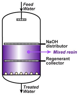
A mixed bed in service
Strongly acidic cation resin is mixed with strongly basic anion resin. The quality of treated water is excellent, typically with a conductivity of less than 0.1 µS/cm and a residual silica of less than 10 or even down to 1 µg/L when properly designed and operated. The resins must however be separated for regeneration. This is a delicate and lengthy operation.
Regeneration involves the following steps:
- Backwash for separation
- Settling
- Acid injection from the bottom, extraction through the middle collector
- Acid displacement
- Caustic injection from the ad hoc distributor, extraction through the middle collector
- Caustic displacement
- Air mixing
- Final fast rinse
Regeneration of a mixed bed unit is not efficient, due to the shallow bed depth of the components and the resulting hydraulic distribution problems. Mixed bed vessels are also more complicated than single bed units. For this reason, mixed bed units are mostly used to treat water with very low salinity, as in this case cycles are reasonably long and chemical efficiency is thus not critical.
Mixed bed units used to treat water with more than traces of salinity are usually called "Working MBs".
Mixed bed polishers are often designed based on specific flow rate in BV/h rather than on salinity and running time.
See also the section about water polishers in the page about water treatment processes.
Spherical units
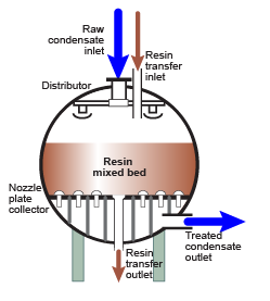
A spherical vessel
Some power stations have condensate polishers operating under high pressure: 4 to 5 MPa (40 to 50 bar, 600 to 700 psi). In this case the shell of the vessel must be very thick. For this reason spherical vessels are built, because a sphere has a better resistance to pressure than a cylinder, and one can save in the thickness of the vessel shell. Those have disadvantages compared to cylindrical columns, as the flow through the resin bed is less uniform.
See the condensate polishing page.
TriobedTM units
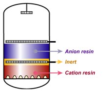
A Triobed after separation
Triobed is a trademark of Rohm and Haas. The concept was developed by Duolite in the 1970's, and had immediate success. The idea was to mix a third, inert component to the active SAC and SBA resins. Density and particle size of the three components are precisely adjusted so that the inert forms a separating layer between cation and anion resins after backwash. Click on the adjacent picture for a better understanding of the principle.
Triobed doesn't have only advantages:
- The inert resin has sometimes problems: it may float if there are traces of oil in the water or condensate, or attract air bubbles at the time of backwashing.
- The inert "dilutes" the active resins, and uses space: the total capacity of the bed is reduced.
- The SAC resin is very coarse, which is detrimental to its kinetics, and requires a high backwash flow rate for separation.
For existing Triobed units, only very specific resin combinations are allowed.
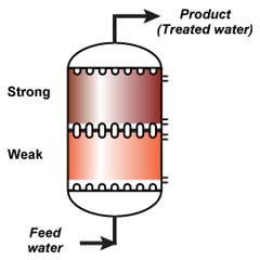
AmberpackTM SandwichTM
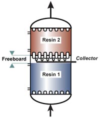
Amberpack Sandwich unit
A different type of polisher, with separate cation and anion resins, not a mixed bed. Amberpack Sandwich polishing units are double chamber Amberpack columns with a strong acid and a strong base resin, separated by a nozzle plate. Twice the efficiency of a mixed bed, and half the size.
The small freeboard (see picture) is usually be filled with a floating inert material. A collector is located just below this separation plate. The advantages of Amberpack Sandwich compared to mixed bed units are:
- As the column is almost full, it contains twice the resin amount, and offers thus a double capacity for the same vessel size.
- As resins are never mixed, all problems of cross-contamination found in MBs are avoided.
- Regeneration is in counterflow mode, thus a much smaller quantity of regenerants is required.
- Sandwich gives the same treated water quality as a conventional MB.
Sandwich units can also be used, like "working MBs", for the treatment of low salinity water, such as RO permeate.
TripolTM
A system with separate resin beds in a single column developed by Permutit (now Veolia). Regeneration is external: the cation resins are transferred to a separate regeneration column. The bottom resin is transferred first, then the top resin on top of it. Therefore, the resin from the bottom compartment receives the maximum acid and is always perfectly regenerated. This system is used for condensate polishing.
MultistepTM
This is an inverted Tripol patented by Bayer AG and operating in floating bed fashion. Regeneration is in situ. Of course, the acid must by-pass the anion resin, so two additional collectors/distributors are necessary. Acid comes from the top, is extracted through the collector just underneath the top compartment, then re-injected through the second distributor just underneath the anion compartment. Inert is required.
Separate columns
A combination of SAC and SBA in separate columns, with co-flow regeneration, was the first kind of polishing installed even before mixed beds became popular.
In Germany, several condensate polishers have been installed with this concept, but the columns are of the floating bed type to maximise efficiency and quality.
Resins used in separate bed polishers
As most of these are packed bed units, uniform grades are recommended. For DI polishers, the standard choice is gel type. For condensate polishers, the hybrid gel cation/macroporous anion combination is recommended.
Construction material
Click the small pictures.
In the laboratory, glass columns are used for resin testing or quality control. See laboratory trials. |

Small units are usually made of fiberglass reinforced plastic. See also SDI. |

Industrial units are made of steel with an internal hard rubber coating. |

In the food industry and some other industries, ion exchange columns are often made of stainless steel. |
Column size
Most industrial ion exchange columns have a diameter between 0.5 and 3.2 m. Bigger vessels with up to 4.0 m are sometimes built, but the aspect ratio of the resin bed (width/height) becomes unfavourable, and very precise distribution and collection systems must be fitted to ensure an even flow of the water during service and regeneration.The limits are related to pressure drop and linear flow rate. See vessel sizing in the page "Principles of plant design". The blue AmberpackTM columns above have a diameter of 2800 mm and contain 10'500 L resin each, the bed depth being 1710 mm, for a flow rate of 200 m3/h per unit (32.5 m/h linear velocity).
Nozzles
The various column pictures on this page show different types of distribution and collection systems. Plates fitted at the bottom — and sometimes at the top — of the vessels with good quality nozzles are efficient distributors and collectors.
A nozzle plate with stiffening beam
Fractal distribution
Fractal distributors are an interesting innovation. They produce a very homogeneous flow, much better than the old-fashioned "header and laterals" distribution systems. The principle is illustrated in the picture on the left: all distribution orifices are at exactly the same distance from the central distribution opening. The pressure drop is thus constant across the whole distributor. On the right, you see a commercial example with a diameter of 1200 mm.
Small fractal

Large fractal
Click to enlarge

Columns with fractal distribution (click)
The columns have a flat bottom, not a dished end. The system is also equipped with membrane degasifiers.


