


Ion exchange plant design
Some basic principles
You will not find here a complete plant design manual. Only a few general recommendations to ensure that an ion exchange system is designed economically and to achieve good performance, and a simple, but detailed example. Basic column types are shown in another page.Reputable water treatment companies have their own technologies and design methods. We will cover in this page some of the basic parameters to consider when designing an ion exchange plant.
These parameters are:
- Feed water analysis
- Production flow rate
- Cycle length
- Required quality of the treated water
- Regeneration technology
- Dimensions of the vessels
- Selection of resin types
Analysis of the feed water
All ion exchange systems are designed for a given feed water. Some variations of the feed water analysis are acceptable, and should be taken into account, but an ion exchange system cannot be designed efficiently for vastly different water types. For instance, a demineralisation system designed for the treatment of deep well water is completely different from a system designed to treat reverse osmosis permeate.
 The first thing to do is thus obtain a reliable water analysis. Details are shown in another page.
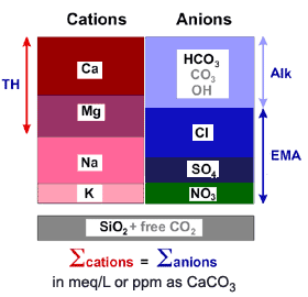
When the water analysis is not constant, e.g. due to seasonal variations, do not take an "average composition" as the basis of your design. Instead, use the "most probable" case, design with this water, and check as a second step what will happen with the "minimum" and "maximum"' waters. All water analyses must be perfectly balanced, as shown in the example on the right.
The water analysis will determine what resin combination is required, and if a degasifier should be considered.
Production flow rate
It is important to know whether the system will operate at constant or variable flow rate. Some system designs require a minimum flow rate (e.g. AmberpackTM). Obviously, the system should be able to operate at both limits.
In general, it is not advisable to operate intermittently, i.e. to stop production in the middle of the run and re-start it. Treated water quality may be affected after a stop not followed by regeneration.
Cycle length
A short cycle length is desirable in most cases. The practical limit is that the production run should be at least as long as the regeneration process. As most ion exchange systems are regenerated automatically, the duration of the production run does not have to be "at least one day" as was the rule at the time (many decades ago) when the morning shift would regenerate manually every day at 7 o'clock. Efficient systems have been designed with running times as short as 3 hours.
The limits of the running time are also related to resin kinetics. When reading ion exchange resin product data sheets, you will typically see that the specific flow rate in water treatment should be between 5 and 50 bed volumes per hour (m3/h per m3 of resin). At lower flow rates, hydraulic distribution in the resin bed may be poor, and at higher flow rates, kinetic effects may affect the speed of exchange, resulting in both cases in deterioration of the treated water quality.
So in practice the running time must be selected as a function of the following parameters:
- Specific flow rate between 5 and 50 bed volumes per hour (BV/h).
- Mixed bed units should be designed to operate at a minimum of 12 to 15 BV/h.
- Make the system as small as possible for economical reasons (lower investment in hardware and resins).
- For packed bed systems, ensure that bed compaction is good both in the production phase (e.g. AmberpackTM) and during regeneration (e.g. UpcoreTM).
With low salinity waters, e.g. when the feed water is good RO permeate, the running time can be several days. Mixed bed polishers after a primary demineralisation will run for several weeks before regeneration is required.
See the description of a full cycle.
Treated water quality
In ion exchange the quality of the treated water does not depend much on the feed water analysis. Factors affecting the treated water quality are essentially related to the regeneration process.
To a minor extend, temperature may affect the residual silica leakage in the treated water: at temperatures higher than about 50 °C, silica is hardly removed by strongly basic anion exchange resins (SBA).
Other than that, you can expect the treated water quality of a regeneration system regenerated in reverse flow to be:
- Conductivity: ~ 1 µS/cm
- Silica: 10 to 25 µg/L
Regeneration technology
Details of the regeneration are given in a separate page. Another page shows the corresponding column designs.
Except for very small ion exchange units (and for de-alkalisation with a WAC resin only), plants should always be designed using reverse flow regeneration. Packed bed columns are particularly useful, as they offer a compact and economical design, and very good treated water quality. They are normally sized for relatively short cycles.
One should however pay attention to the following points:
AmberpackTM and other floating bed columns
Those have upflow loading and downflow regeneration. The service flow rate must be high enough to keep the bed compacted. For SAC resins, that have the highest specific gravity, the linear flow rate must be comprised between 25 and about 70 m/h (at about 20 °C). Other resins have a lower specific gravity and are compacted at a lower flow rate, the minimum being about 16 m/h.
UpcoreTM and similar units
With downflow loading and upflow regeneration, the regeneration flow rate must be high enough to keep the bed compacted. This is achieved using the following tricks:
- An initial short compaction step is performed at about 30 m/h before regenerant injection
- Regenerant concentration may have to be reduced so that the acid solution can be injected at 7 or more m/h in the SAC unit, and the caustic solution at more than 5 m/h in the anion exchange unit.
- Contact time of the regenerant solution may have to be reduced.
Vessel sizing
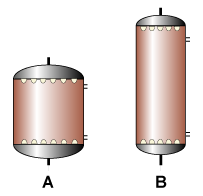 For a given resin volume, it is generally cheaper to make a tall and narrow column rather than a wide and short unit: in the illustration, both columns contain the same resin volume. Column B is cheaper, because the major cost components of the column are the dished ends and nozzle plates.
There is no limit in height, except that the pressure drop at maximum flow rate should not exceed 100 to 150 kPa (1 to 1.5 bar) at maximum flow rate with clean resins.
When selecting the vessel diameter, the limits of the preceding section (regeneration technology) should also be considered.
Resin choice
You will have to refer to the resin manufacturer. However, a few general recommendations can be made:
- Macroporous resins are normally not required for demineralisation or softening
- An exception: all styrenic WBA resins are macroporous
- Special particle sizes are required depending on the design technology:
- uniform or semi-uniform resins are necessary for packed beds
- special grades are required for stratified beds (e.g. StratabedTM or StratapackTM)
- special grades are also required for mixed bed polishers
- When the feed water contains high organics, acrylic anion resins are a good choice
How to calculate by hand, approximately
You can make an approximate calculation by hand even without using a computer program or the engineering data of the resin manufacturer. The results may be only 20 % precise, but will give you an idea. In any case, it is a good exercise for understanding the basic principles presented above.
This calculation can be done for softening units and for simple demineralisation trains comprising a single (strongly acidic) cation exchange resin column an optional degasifier and a single (strongly basic) anion exchange resin column.
Here is the procedure for a simple demineralisation plant:
- Examine water analysis (details above)
- Calculate cation concentration Cc [meq/L]
- Decide about the use of a degasifier:
If the bicarbonate content is greater than 0.6 to 1.0 meq/L a degasifier may be justified - Calculate the anion concentration Ca [meq/L]: it contains
Cl—, SO4=, NO3—, SiO2, HCO3— or residual CO2 after degasser if any - Decide about a reasonable running time t in hours between regenerations
- Using the flow rate f in m3/h calculate the throughput Q [m3]:
Q = f · t [m3] - Calculate the ionic load per cycle in eq (concentration in meq/L times throughput in m3):
- Cation load [eq] = Cc · Q
- Anion load [eq] = Ca · Q
- Consider the approximate operating capacity of the resins as follows:
- SAC: capc = 1.0 eq/L with HCl regeneration or
SAC: capc = 0.8 eq/L with H2SO4 regeneration - SBA: capa = 0.5 eq/L
- SAC: capc = 1.0 eq/L with HCl regeneration or
- The resin volume V required (in litres) is equal to the ionic load [eq] divided by the operating capacity [eq/L]:
- SAC: Vc = Cc · Q / capc [L]
- SBA: Va = Ca · Q / capa [L]
- At the end of this calculation, we must make sure that the specific flow rate of both resin columns is compatible with the general recommendations of the resin producer. The specific flow rate in h–1 (often expressed in bed volumes per hour BV/h) is equal to the flow rate in m3/h divided by the resin volume in m3. The usual range is 5 to 50 h–1. For a compact plant with minimum investment cost, use a specific flow rate around 30 to 35 h–1.
If the specific flow rates calculated from the resin volumes Vc and Va are too high, increase the running time t. If they are too low, reduce the running time t.
Furthermore, the additional ionic load caused by the quantity of ancillary water required to dilute regenerants and rinse resins has not been taken into account. Depending on the feed water salinity, this extra water can increase the ionic load by 2 to 10 %.
Besides, the calculation of WAC/SAC or WBA/SBA resin couples cannot be done by hand, as it requires iterations for the optimisation of the "overrun".
A precise calculation can be done with a dedicated software, such as IXCalcTM for the resins produced by Dow.
Example
 Using the 10 point procedure described above.
- Water analysis [meq/L]
Cations Anions Ca 3.2 Cl 1.1 Mg 0.7 SO4 0.6 Na 0.9 NO3 0.2 HCO3 2.9 Σ Cations 4.8 Σ Anions 4.8 SiO2 0.4 - Cc = 4.8 meq/L
- HCO3 = 2.9 meq/L — a degasifier is recommended
Residual CO2 after degasifier = 0.25 meq/L - Ca = 1.1 + 0.6 + 0.2 + 0.25 = 2.15 meq/L
- Select running time t = 12 h
- Flow rate 60 m3/h
Throughput 60 · 12 = 720 m3 - Ionic load
- Cation load [eq] = 4.8 · 720 = 3456 eq
- Anion load [eq] = 2.15 · 720 = 1548 eq
- Operating capacity
- Cation regeneration with HCl: capc = 1.0 eq/L
- Anion regeneration with NaOH: capa = 0.5 eq/L
- Resin volumes
- SAC: Vc = 3456 / 1.0 = 3456 L
- SBA: Va = 1548 / 0.5 = 3096 L
- Specific flow rate
- SAC: 60 / 3.456 = 16.9 h–1
- SBA: 60 / 3.096 = 19.4 h–1
- Throughput 60 · 8 = 480 m3
- Cation load [eq] = 4.8 · 480 = 2304
- Anion load [eq] = 2.15 · 480 = 1032 eq
- SAC volume: Vc = 2304 / 1.0 = 2304 L
- SBA volume: Va = 1032 / 0.5 = 2064 L
- SAC flow rate: 60 / 2.304 = 26.0 h–1
- SBA flow rate: 60/2.064 = 29.1 h–1
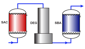
We have assumed in our example (see picture above) that the columns are regenerated in Amberpack mode, which will guarantee a very good treated water quality, with typically less than 1 µS/cm conductivity and less than 10 µg/L residual silica.
Amberpack, Upcore, Stratabed, and Stratapack are trademarks of the Dow Chemical Company.

